 English
 русский
 Français
 中文简体
中文简体 Português
 Español
 italiano
 عربى
عربى فارسی
فارسیThe anti-blowout stem design in a Quarter Turn Ball Valve prevents catastrophic failure by incorporating a mechanical retention feature — typically a stem shoulder, collar, or enlarged stem end — that physically prevents the stem from being ejected from the valve body when internal pressure exceeds safe limits. This is not a redundant safety feature; it is a primary structural safeguard mandated by standards such as API 6D and ISO 17292 for valves operating in high-pressure and safety-critical services.
Without this design, a stem blowout can occur in milliseconds, turning the valve stem into a high-velocity projectile capable of causing fatal injuries and catastrophic process leaks. Understanding exactly how this mechanism works — and why it matters — is essential for any engineer specifying or operating a Quarter Turn Ball Valve in demanding applications.
What Causes Stem Blowout in a Quarter Turn Ball Valve
A stem blowout occurs when the axial force exerted by the process fluid on the stem exceeds the mechanical resistance holding it in place. In a conventional Quarter Turn Ball Valve, the stem passes through a stuffing box or packing gland in the valve body. If the packing degrades, corrodes, or is improperly installed, internal pressure can act directly on the exposed cross-sectional area of the stem.
For a valve with a stem diameter of 25 mm operating at 100 bar (1,450 psi), the axial blowout force on the stem can exceed 4,900 N (approximately 500 kgf). Without a positive retention mechanism, this force is enough to expel the stem violently from the body. Historical incidents in the oil and gas industry have documented fatalities directly resulting from unretained stem blowouts during routine maintenance operations where lines were believed to be depressurized but were not.
How the Anti-Blowout Stem Design Works
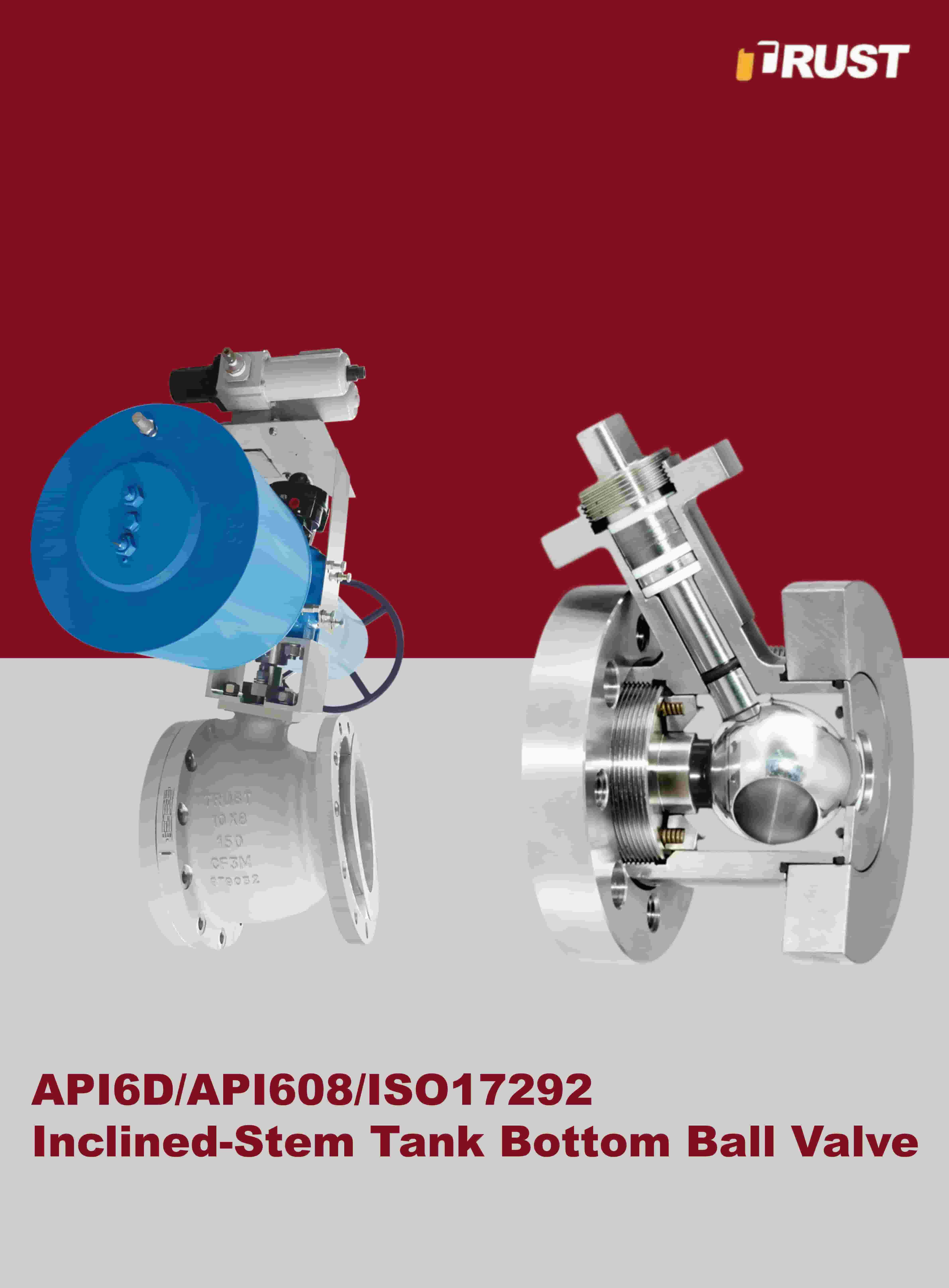
The anti-blowout feature in a Quarter Turn Ball Valve is achieved through the geometry of the stem itself. Rather than inserting the stem from outside the valve body (top-entry without retention), a bottom-loaded or internally retained stem design is used. The stem is inserted from inside the pressure boundary during assembly, and an integral shoulder or T-shaped profile prevents it from passing outward through the packing bore.
Key Geometric Features
- Stem shoulder (anti-blowout collar): A machined flange or step on the stem that is wider than the stem bore in the body. This collar bears against the internal surface of the valve body, creating a positive mechanical stop against outward ejection.
- T-bar or D-profile stem end: Some designs use a T-shaped lower end that interlocks with the ball socket, ensuring the stem cannot travel axially unless the entire body is disassembled.
- Retained stem nut or snap ring: In certain Quarter Turn Ball Valve designs, a secondary retaining ring inside the body provides an additional mechanical barrier, supplementing the primary collar.
In all cases, the critical principle is the same: the stem retention must be achieved by the valve body geometry itself, not solely by packing compression or fastener torque. Packing can fail; a machined shoulder integral to the stem cannot be bypassed by packing degradation.
Anti-Blowout Stem vs. Conventional Stem: A Direct Comparison
| Feature | Conventional Stem | Anti-Blowout Stem |
|---|---|---|
| Retention mechanism | Packing compression only | Mechanical shoulder / T-bar |
| Blowout risk on packing failure | High | Negligible |
| Assembly method | Top-down insertion | Bottom-loaded / internal |
| Compliance with API 6D / ISO 17292 | Not typically compliant | Fully compliant |
| Suitable for high-pressure service | Not recommended | Yes |
| Live-loading / adjustable packing | Optional | Standard in Class 600+ valves |
Standards and Testing Requirements for Anti-Blowout Stems
Reputable Quarter Turn Ball Valve manufacturers design and test anti-blowout stems in accordance with internationally recognized standards. These standards define both the design requirement and the verification test method.
- API 6D (Pipeline and Piping Valves): Explicitly requires that the stem design must retain the stem within the valve body under full rated pressure even with packing completely removed.
- ISO 17292 (Metal ball valves for petroleum, petrochemical, and allied industries): Mandates anti-blowout stem construction for valves used in hazardous process services.
- ASME B16.34: Governs pressure-temperature ratings and indirectly supports anti-blowout stem requirements through body integrity provisions.
- API 607 / ISO 10497 (Fire testing): Fire-safe tested Quarter Turn Ball Valve designs must demonstrate that the stem does not blow out during fire exposure, where soft packing materials may melt or char.
Verification testing typically involves removing all packing from the stuffing box and applying 1.1 times the maximum allowable working pressure (MAWP) to the valve body while confirming zero stem movement. This is the definitive proof that retention is geometric — not packing-dependent.
The Role of Stem Packing in Conjunction with Anti-Blowout Design
While the anti-blowout collar eliminates the ejection risk, the stem packing system in a Quarter Turn Ball Valve remains critical for sealing process fluid at the stem-to-body interface. These two elements serve distinct but complementary functions: the collar retains the stem structurally; the packing prevents fugitive emissions.
Common Packing Materials and Their Operating Ranges
- PTFE (Virgin or Filled): Suitable for temperatures up to 200°C (392°F); ideal for chemical service in a Quarter Turn Ball Valve handling aggressive media.
- Graphite packing: Rated for temperatures exceeding 500°C (932°F) and high-pressure steam service; commonly used in high-class fire-safe designs.
- Live-loaded spring packing: Uses a Belleville washer stack to maintain constant packing compression as the packing wears, reducing fugitive emission rates below 100 ppm in compliance with ISO 15848 and EPA Method 21.
In high-cycle applications — such as a Quarter Turn Ball Valve actuated hundreds of times per day in a process plant — live-loaded packing is strongly recommended because it compensates for packing wear without manual retightening, while the anti-blowout collar independently ensures stem retention regardless of packing condition.
Trunnion-Mounted vs. Floating Ball: Impact on Stem Blowout Risk
The ball support design of a Quarter Turn Ball Valve also influences the mechanical loading on the stem and, consequently, the blowout risk profile.
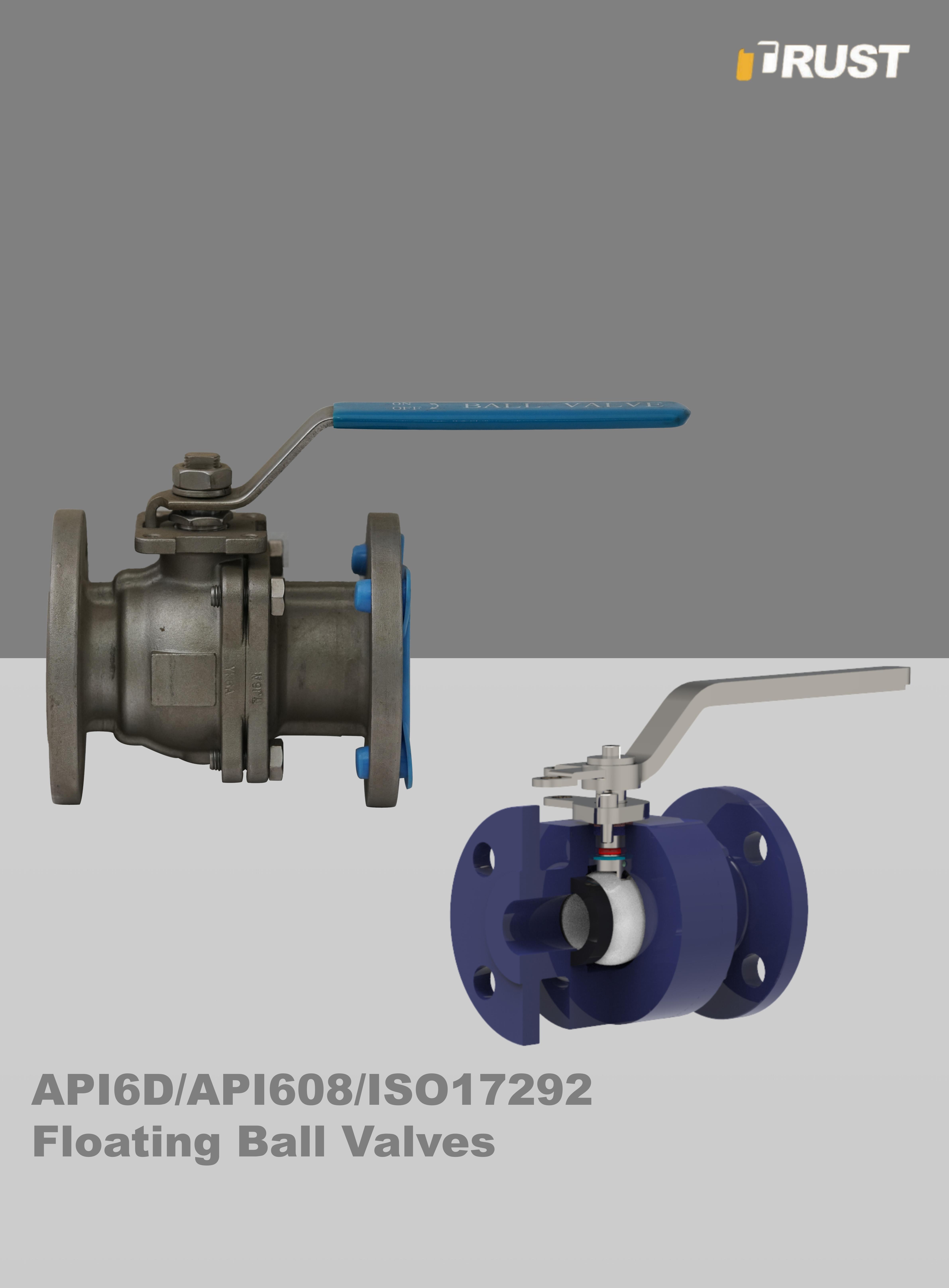
In a floating ball Quarter Turn Ball Valve, the ball is not mechanically fixed; it floats and is pushed against the downstream seat by line pressure. The stem transmits torque to the ball and is subject to some lateral loading. In smaller sizes (typically DN 15 to DN 100 / NPS ½" to 4"), this design is common and economical, but at higher pressures, the resultant forces on the stem increase significantly.
In a trunnion-mounted Quarter Turn Ball Valve, the ball is anchored both at the stem (top trunnion) and at the bottom trunnion pin. This distributes the pressure loading away from the stem dramatically, reducing stem side-loading by as much as 60–70% in large-bore, high-pressure applications (Class 600 and above, or DN 150+). The anti-blowout stem collar design is equally critical in both configurations, but trunnion mounting significantly reduces the mechanical stress on the stem during pressurized operation.
Practical Inspection and Verification for End Users
When procuring or commissioning a Quarter Turn Ball Valve for high-pressure service, engineers should perform or request the following verifications to confirm that the anti-blowout design is genuinely implemented:
- Request cross-sectional assembly drawings showing the stem shoulder geometry and its bearing surface within the valve body. Confirm the shoulder diameter exceeds the stem bore diameter by a defined engineering margin.
- Verify standard compliance documentation — specifically, the manufacturer's declaration of conformance to API 6D or ISO 17292 with anti-blowout stem explicitly referenced.
- Review test certificates showing the stem retention test was conducted without packing at rated pressure, per API 6D Annex F or equivalent procedure.
- Inspect the physical valve upon delivery: attempt to pull the stem outward by hand after packing gland removal (with valve depressurized). In a properly designed Quarter Turn Ball Valve, the stem should be retained by the shoulder and unmovable in the axial outward direction.
- Confirm material traceability of the stem material. For sour service environments (H₂S-containing media), stem material must comply with NACE MR0175 / ISO 15156 to prevent sulfide stress cracking, which could compromise stem integrity independently of the anti-blowout collar.
Why Anti-Blowout Stem Design Is Non-Negotiable in Critical Services
The anti-blowout stem is not a premium option in a Quarter Turn Ball Valve — it is a baseline safety requirement for any valve installed in services where process fluid is flammable, toxic, high-pressure, or at elevated temperature. Regulatory bodies including OSHA (Process Safety Management, 29 CFR 1910.119) and the European Pressure Equipment Directive (PED 2014/68/EU) require that valves in Category III and IV pressure systems incorporate design features that prevent sudden, uncontrolled release of contained energy.
A Quarter Turn Ball Valve without a verified anti-blowout stem design should never be installed in oil and gas pipelines, chemical processing units, power generation steam systems, or any service above Class 150 (PN 20) where a sudden stem ejection would create an unacceptable safety hazard. The incremental cost of specifying a properly retained stem design is negligible compared to the potential liability, downtime, and human cost of a preventable blowout event.
 No.100 Xiejin Avenue, Funing County Economic Development Zone, Yancheng City, Jiangsu Province
  +86-515-87398111
  office@trustvalve.com